Weixin Service

 DouYin
 KuaiShou

Explanation of common parameters and test essentials of MCU for new energy vehicles
Date:2022-03-25 15:01:00Views:1366
Micro controller unit (MCU), also known as single chip microcomputer or single chip microcomputer, is to appropriately reduce the frequency and specification of central process unit (CPU), and integrate peripheral interfaces such as memory, counter, USB, a / D conversion, UART, PLC, DMA and even LCD drive circuit on a single chip to form a chip level computer, Do different combination control for different applications. MCU is the unique core power electronic unit of new energy vehicles. By receiving the vehicle driving control command from VCU, MCU controls the motor to output the specified torque and speed to drive the vehicle. It can convert the DC energy of the power battery into the required high-voltage AC, and drive the motor body to output mechanical energy. At the same time, MCU has the functions of motor system fault diagnosis, protection and storage. MCU has many setting parameters, and each parameter has a certain selection range. In use, MCU can not work normally due to improper setting of individual parameters (parameter setting is set through can communication or simulator). Therefore, relevant parameters must be set correctly.
1. Control mode:
That is, speed control, torque control, PID control or other methods. After the control mode is adopted, the static or dynamic identification shall be carried out according to the control accuracy.
2. Minimum operating frequency:
That is, the minimum speed of the driving motor. When the driving motor runs at low speed, its heat dissipation performance is very poor (air-cooled type). If the motor runs at low speed for a long time, it will cause the driving motor to burn out. Moreover, at low speed, the current in the cable will also increase, which will also lead to cable heating.
3. Maximum operating frequency:
The maximum frequency of general MCU is up to 60Hz, and some even up to 400Hz. High frequency will make the driving motor run at high speed. For ordinary motor, its bearing cannot run at over rated speed for a long time. Can the rotor of the motor bear such centrifugal force.
4. Carrier frequency:
The higher the carrier frequency is set, the greater the higher harmonic component, which is closely related to the length of cable, motor heating, cable heating, IGBT heating and other factors.
5. Motor parameters:
MCU sets the power, current, voltage, speed and maximum frequency of the motor in the parameters, which can be directly obtained from the nameplate of the driving motor.
6. Frequency hopping:
Resonance may occur at a certain frequency point, especially when the whole device is relatively high; When controlling the compressor, avoid the surge point of the compressor (air conditioning compressor).
7. Acceleration and deceleration time
Acceleration time is the time required for the output frequency to rise from 0 to the maximum frequency, and deceleration time is the time required for the output frequency to fall from the maximum frequency to 0. The acceleration and deceleration time is usually determined by the rise and fall of the frequency setting signal. When the driving motor accelerates, the rising rate of the frequency setting must be limited to prevent overcurrent, and when decelerating, the falling rate must be limited to prevent overvoltage.
Acceleration time setting requirements: limit the acceleration current below the overcurrent capacity of MCU to prevent overcurrent stall from causing power failure protection of high-voltage system; The key points for setting the deceleration time are to prevent the voltage of the smoothing circuit from being too large, so as not to make the regeneration overvoltage stall and cut off the power of the high-voltage system for protection. The acceleration and deceleration time can be calculated according to the load, but in commissioning, it is often used to set a long acceleration and deceleration time according to the load and experience, and observe whether there is overcurrent and overvoltage alarm by starting and stopping the driving motor; Then shorten the acceleration and deceleration setting time gradually, and repeat the operation for several times based on the principle of no alarm during operation, so as to determine the best acceleration and deceleration time.
8. Torque lifting
Also known as torque compensation, it is a method to increase the low frequency range f / V in order to compensate for the reduction of torque at low speed caused by the resistance of motor stator winding. When it is set to automatic, the voltage during acceleration can be increased automatically to compensate the starting torque and accelerate the driving motor smoothly. According to the load characteristics, especially the starting characteristics of the load, the better curve can be selected through the test. For variable torque load, if it is not selected properly, the output voltage at low speed will be too high and electric energy will be wasted. Even when the driving motor starts with load, the current will be large and the speed will not go up.
9. Electronic thermal overload protection
The CPU calculates the overheat protection value of the motor according to the overheat protection frequency of the motor. This function is only applicable to "one by one" occasions.
Electronic thermal protection setting value (%) = [motor rated current (a) / MCU rated output current (a)] × 100% 。
10. Frequency limit
That is, the upper and lower limits of MCU output frequency. Frequency limit is a protection function to prevent the output frequency from being too high or too low due to misoperation or failure of external frequency setting signal source, so as to prevent damage to the equipment. In the application, it can be set according to the actual situation. This function can also be used as a speed limit to set the upper limit frequency of MCU to a certain frequency value, so as to make the maximum speed at a fixed and low working speed.
11. Torque limit
It can be divided into driving torque limit and braking torque limit. According to the output voltage and current of MCU and the torque calculation by CPU, it can significantly improve the impact load recovery characteristics during acceleration, deceleration and constant speed operation. The torque limiting function can realize automatic acceleration and deceleration control. Assuming that the acceleration and deceleration time is less than the load inertia time, it can also ensure that the drive motor can automatically accelerate and decelerate according to the torque setting value.
The driving torque function provides a powerful starting torque. During steady-state operation, the torque function will control the motor slip and limit the motor torque to the maximum set value. When the load torque suddenly increases, even if the acceleration time is set too short, it will not cause the power-off protection of the high-voltage system. When the acceleration time is set too short, the motor torque will not exceed the maximum set value. Large driving torque is favorable for starting, and it is better to set it to 80 ~ 100%.
The smaller the set value of braking torque, the greater the braking force. It is suitable for the occasion of rapid acceleration and deceleration. For example, if the set value of braking torque is set too much, there will be overvoltage alarm. If the braking torque is set to 0%, the total amount of regeneration added to the main capacitor can be close to 0, so that when the drive motor is decelerated, it can be decelerated to stop without using the braking resistance, and there will be no overvoltage protection. However, on some loads, for example, when the braking torque is set to 0%, there will be short-term idling during deceleration, resulting in repeated starting of MCU and large fluctuation of current. In serious cases, MCU will report fault, which should be paid attention to.
_20220325145818_514.jpg "新能源汽车MCU常用参数及测试要领讲解")
Summary of test Essentials
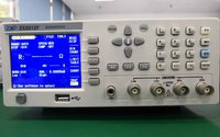
1. MCU working voltage and current
Test whether the working voltage of MCU is within the working voltage range. If the voltage is too high, it will affect the normal operation of MCU or even burn out. If the working voltage is too low, it will affect the driving ability of MCU peripheral circuit, and even cause the peripheral circuit to not work normally.
2. MCU quiescent current
Quiescent current is one of the main parameters to measure the performance of MCU. The smaller the quiescent current is, the better. Test whether the quiescent current meets the requirements according to the MCU specification. Once the MCU is damaged, the quiescent current will increase, which will increase the static consumption of the product and increase the overall power consumption of the product.
3. Oscillation frequency of MCU
If the MCU is of external crystal oscillator type, it is necessary to check whether the oscillation frequency of the crystal oscillator input pin of the MCU is correct during its normal operation. If the oscillation frequency of the crystal oscillator does not meet the requirements, it will affect the timing and delay of the product, or even fail to work normally.
Combined function test of products (MCU online system test)
1. Test the perfection of MCU software function. This is a test for the functions of all single chip microcomputer systems, and whether the test software is written correctly and completely.
2. Power on and power off test. In use, users will inevitably encounter power on and power off. They can switch the power supply for many times to test the reliability of the single chip microcomputer system.
3. Aging test. Test the reliability of single chip microcomputer system under the condition of long-time operation. If necessary, it can be tested in the environment of high temperature, high voltage and strong electromagnetic interference.
4. ESD, EFT and other tests. Various interference simulators can be used to test the reliability of single chip microcomputer system. For example, use electrostatic simulator to test the anti-static ESD ability of single chip microcomputer system; Fast pulse anti-interference EFT test using burst noise simulator, etc.
It can also simulate the possible damage in human use. For example, the human body or clothing fabric is used to deliberately rub the contact port of the single chip microcomputer system, so as to test the anti-static ability. The high-power electric drill is used to work close to the single chip microcomputer system, so as to test the ability of anti electromagnetic interference.
The above is related to the common parameters and test essentials of MCU of new energy vehicles compiled by Chuangxin testing team. I hope it will be helpful to you. Chuangxin testing is a professional testing organization for electronic components. At present, it mainly provides integrated circuit testing services such as capacitance, resistance, connector, MCU, CPLD, FPGA, DSP and so on. Specializing in functional testing of electronic components, incoming appearance testing of electronic components, anatomical testing of electronic components, acetone testing, X-ray scanning testing of electronic components and RoHS component analysis testing. Welcome to call, we will serve you wholeheartedly!