Weixin Service

 DouYin
 KuaiShou

How to conduct IC failure analysis? Dry goods sorting and sharing
Date:2021-12-02 11:58:00Views:1005
Generally speaking, the failure of integrated circuits is inevitable in the process of development, production and use. With the continuous improvement of people's requirements for product quality and reliability, failure analysis is becoming more and more important. Chip failure analysis can help integrated circuit designers find design defects, mismatch of process parameters or improper design and operation.
IC failure analysis steps:
1. Inspection before opening, appearance inspection, X-ray inspection and scanning acoustic microscope inspection.
2. Open the seal for microscopic examination.
3. Electrical performance analysis, defect location technology, circuit analysis and microprobe analysis.
4. Physical analysis, delamination, focused ion beam (FIB), scanning electron microscope (SEM), transmission electron microscope (SEM), VC positioning technology.
1、 Nondestructive failure analysis
1. Appearance inspection mainly relies on visual inspection to check whether there are obvious defects, such as whether the plastic grease package is cracked and whether the chip pins are in good contact.
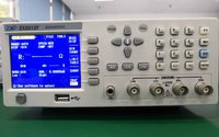
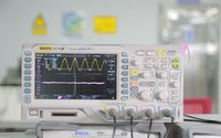
2. X-ray inspection is to irradiate the tested sample with X-ray perspective performance. The defective part of the sample will absorb X-ray, resulting in abnormal X-ray irradiation imaging. X-ray is mainly used to check whether the IC lead is damaged. Select the appropriate wavelength according to the size and structure of electronic components, so as to obtain the appropriate resolution.
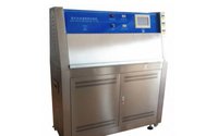
3. Scanning acoustic microscope detection is to use ultrasonic wave to detect the internal defects of the sample and find out the location of the internal defects of the sample according to the reflection of ultrasonic wave. This method mainly uses the damage of moisture or high temperature to the device during plastic packaging of the main integrated circuit, which is often crack or delamination.
2、 Destructive failure analysis
1. Open the package
Lossy failure analysis, the first is to unpack the integrated circuit, which should not damage the internal circuit of the chip. According to the different packaging methods or analysis purposes of integrated circuits, corresponding unsealing measures shall be taken. There are usually three ways to open the package.
Method 1: full stripping method, which is to completely damage the integrated circuit and leave only the complete internal circuit of the chip. The defect is that the internal circuit and leads are all damaged, so the electromotive state analysis can no longer be carried out.
Method 2, local total elimination method, which uses a grinder to grind the resin on the surface of the integrated circuit until the chip. The utility model has the advantages that the internal circuits and leads are not damaged during the unsealing process, and the power on dynamic analysis can be carried out after unsealing. Method 3 is a fully automatic method, which uses sulfuric acid injection to achieve the effect of local removal.
2. Electrical analysis
① Defect location, locating specific failure location is an important and difficult project in integrated circuit failure analysis. Failure mechanism and defect characteristics can be found only after defect location.
a. Emission microscope technology has the characteristics of non-destructive, fast and accurate. It uses optoelectronic detectors to detect areas where optoelectronic effects occur. Due to the defects in the silicon wafer, the increasing electron hole recombination usually occurs, resulting in strong photon radiation.
b. OBIRCH technology is a measurement technology that uses laser beam to induce the change of material resistivity. By scanning different materials with laser beam, the resistivity changes of different materials can be obtained. This method can test the reliability hidden dangers in metal wiring.
C. Liquid crystal hot spot detection is generally composed of polarizing microscope, sample table with adjustable temperature and control circuit. When changing from crystal anisotropy to crystal isotropy, the critical temperature energy required is very small, so as to improve the sensitivity. At the same time, the phase transition temperature should be controlled at 30-90 degrees, and the polarization microscope should be used in orthogonally polarized light, which can improve the sensitivity of liquid crystal phase transition reaction.
② Electrical performance analysis (probe table)
According to the layout and schematic diagram of the decorative circuit, combined with the chip failure phenomenon, gradually reduce the circuit range of the defective part, and finally use the microprobe microscopy technology to locate the defective device.
③ Microprobe detection technology
The function of microprobe is to measure the electrical parameters of internal devices, such as working point voltage, current and volt ampere characteristic curve. Microprobe technology is generally used together with circuit analysis, which can quickly search for failed devices.
_20211202115809_275.jpg "怎么进行集成电路失效分析?干货整理分享")
3、 Physical analysis
1. Focused ion beam (FIB)
It is a cutter that focuses ions into microwave size by electron microscope. The focused ion beam system consists of ion source, ion beam focusing and sample stage. The main application of focused ion beam is to profile the integrated circuit. The traditional method is manual grinding or sulfuric acid spray. Although both methods can obtain the profile, in the increasingly fine integrated circuit, the manual operation speed is slow and the error rate is high. Therefore, this method is obviously not applicable. The fine and accurate cutting of focused ion beam, combined with the high-resolution imaging of scanning electron microscope, can well solve the profile problem. The focused ion beam has no limit on the integrated circuit to be profiled, and the positioning accuracy can reach less than 0.1um. At the same time, the stress of the integrated circuit in the profile process is very small, so the integrated circuit can be completely saved to make the detection results more accurate.
2. Scanning electron microscope (SEM)
By bombarding the device surface with focused ion beam, many electronic signals are generated. These electronic signals are amplified as modulation signals and connected to the display to obtain the device surface image.
3. Transmission electron microscope (TEM)
The resolution of transmission electron microscope can reach 0.1nm. Transmission electron microscope can clearly analyze device defects and better meet the analysis requirements of integrated electrical failure analysis for detection tools.
4. VC positioning technology
Using emission / OBIRCH / liquid crystal technology to locate the failed devices in integrated circuits, in practical applications, the location of hot spots is often too large, and even deviates from the failure point by dozens of microns, which requires a more accurate positioning technology, which can further reduce the failure range. VC positioning technology is to scan the sample surface with primary electron beam or ion beam of SEM or fib. There are different potentials at the missing parts of the silicon wafer surface, showing different bright contrast. Find out the points that are normally bright, so as to locate the failure point.
4、 Integrated circuit failure analysis steps
1. Inspection before opening, appearance inspection, X-ray inspection and scanning acoustic microscope inspection.
2. Open the seal for microscopic examination.
3. Electrical performance analysis, defect location technology, circuit analysis and microprobe analysis.
4. Physical analysis, delamination, focused ion beam (FIB), scanning electron microscope (SEM), transmission electron microscope (SEM), VC positioning technology.
The above is the related content of "integrated circuit failure analysis" brought by the core creation test. I hope it will be helpful to you. We will bring more wonderful content in the later stage. Our testing services include: electronic component testing and verification, IC true and false identification, product design and material selection, failure analysis, function testing, factory incoming material inspection, tape braiding and other testing items. Warmly welcome to call, we will serve you wholeheartedly.