Weixin Service

 DouYin
 KuaiShou

Welding and disassembly methods and precautions of SMT chip components
Date:2021-10-12 15:00:00Views:1769
At present, many household appliances and instruments use various patch components. In the process of technical welding, there are various specific requirements for welding things and welding materials. In the process of SMT electronic manufacturing, it is inevitable to present small probability maintenance caused by abnormal materials, bad solder, solder paste, etc. So, do you know the use of electronic welding related knowledge? Welding and disassembly methods and precautions of components let's have a look!
SMT patches are generally not easy to remove machined parts. It needs continuous practice to grasp, otherwise it is easy to destroy SMT components by forcible removal. The welding disassembly techniques for SMT patch processing are as follows:
1. Suitable for SMD components with few pins, such as resistance, capacitance, diode, triode, etc. First tin the PCB with a pad between them, then fix the components in the installation position with tweezers in the left hand, lean against the circuit board, and solder the pins on the tinned pad with a soldering iron in the right hand. The left-hand tweezers can be loosened, and the remaining feet can be welded with tin wire instead. If it is easy to disassemble this part, just heat both ends of the part with a soldering iron, and then quietly lift the part after the tin melts.
2. A similar approach is adopted for SMT chip machined components with more pins and SMT chip components with wider distance. Tin the solder pad first, then clamp the components with tweezers in your left hand and weld one leg, and the remaining legs are welded with tin wire. In general, it is best to use a hot-air gun to disassemble these parts. One hand holds the hot-air gun to blow the solder, and the other hand takes out the components with clamps such as tweezers when the solder melts.
3. For components with high pin density, the welding process is similar, that is, first weld one pin, and then weld other pins with tin wire. The number of pins is large and dense, and the alignment of pins and pads is the key. Generally, the pads on the corners are plated with small tin. Use tweezers or hands to align the assembly with the pad and the edge with pins. Quietly press the components on the PCB and solder the corresponding pins of the pad with a soldering iron.
Finally, the components with high pin density are mainly disassembled with a hot-air gun, clamp the components with tweezers, blow all pins back and forth with a hot-air gun, and lift them after the components melt. If the parts need to be removed, try not to face the center of the parts during blowing, and the time should be as short as possible. After removing the components, clean the pads with a soldering iron.
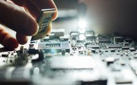
_20211012141508_492.jpg "SMT贴片元器件焊接拆卸方法及注意事项")
Let's talk about the precautions for welding operation:
(1) Keep the soldering iron head clean
During welding, the soldering iron head is in a high temperature state for a long time, and contacts with weak acidic substances such as flux. Its surface is easy to oxidize and stained with a layer of black impurities. These impurities form a thermal insulation layer, which hinders the heat conduction between the soldering iron head and the weldment. Therefore, pay attention to rub impurities on the soldering iron frame at any time. It is also a common method to wipe the soldering iron head with a wet cloth or sponge at any time.
(2) Heat transfer is accelerated by increasing the contact area
When heating, all parts of the weldment that need solder infiltration should be heated evenly, not just a part of the weldment, and the method of increasing pressure on the weldment with a soldering iron should not be used to avoid damage or hidden dangers that are not easy to detect. Some beginners try to speed up welding and apply pressure on the welding surface with a soldering iron head. Indeed, the method is to select different soldering iron heads according to the shape of the weldment, or trim the soldering iron head by themselves, so that the soldering iron head forms surface contact with the weldment rather than point or line contact. In this way, the efficiency can be greatly improved.
(3) Solder bridge for heating
In non assembly line operation, the shapes of solder joints are diverse, and it is impossible to constantly replace the soldering iron head. To improve the heating efficiency, a solder bridge for heat transfer is needed. The so-called solder bridge is to retain a small amount of solder on the soldering iron head as a heat transfer bridge between the soldering iron head and the weldment during heating. Because the thermal conductivity of liquid metal is much higher than that of air, the weldment is quickly heated to the welding temperature. It should be noted that the amount of tin used as a solder bridge cannot be retained too much, so as to avoid misconnection of solder joints.
(4) Pay attention to the removal of soldering iron
The withdrawal of soldering iron shall be timely, and the angle and direction of withdrawal are related to the formation of solder joint (generally 45 degrees).
(5) Do not move until the solder solidifies
Do not move or vibrate the weldment, especially when clamping the weldment with tweezers, be sure to remove the tweezers after the solder solidifies, otherwise it is very easy to cause false welding.
(6) The amount of solder should be moderate
Excessive soldering tin not only unnecessarily consumes more expensive tin, but also increases the welding time and reduces the working speed. More seriously, excessive tin can easily cause imperceptible short circuit fault. Too little solder can not form a solid bond, which is also unfavorable. Especially when welding the lead out of the printed board, the amount of solder is insufficient, which is very easy to cause the lead to fall off.
(7) Do not use a soldering iron head as a tool for carrying solder
Some people are used to soldering with soldering tin on the soldering iron head, resulting in the oxidation of solder. Because the temperature of the soldering iron head is generally about 300 degrees, the flux in the solder wire is easy to decompose and fail at high temperature.
The above is all the contents of the SMT chip component welding and disassembly skills and precautions brought by the core creation test. I hope it can be helpful to you. We will bring more wonderful contents in the later stage. The company's testing services cover: electronic component testing and verification, IC authenticity identification, product design and material selection, failure analysis, function testing, factory incoming material inspection, tape braiding and other testing items. Welcome to call Chuangxin testing, we will serve you wholeheartedly.