Weixin Service

 DouYin
 KuaiShou

Teach you how to detect the quality of IGBT tubes
Date:2024-03-25 16:59:02Views:62
What is IGBT? IGBT, also known as insulated gate bipolar transistor, is a composite fully controlled voltage driven power semiconductor device that is the core device for power control and conversion. It is widely used in high voltage and high current photovoltaic inverters, energy storage devices, and new energy vehicles. IGBT has the characteristics of high input impedance, low conduction voltage drop, high-speed switching characteristics, and low conduction state loss.
IGBT testing project
To test the performance, stability, and reliability of IGBT, IGBT testing is an important part of the design and production process. Through testing, potential early issues can be identified, thereby improving its performance and providing users with a good experience during use.
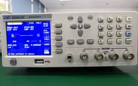
_20240325165541_108.png "教你如何检测IGBT管好坏的方法")
The main projects for IGBT testing include:
Gate emitter threshold voltage VGE (TO) test
Gate emitter leakage current IGES test
ICES testing of collector emitter cut-off current
Collector emitter saturation voltage VCE (sat) test
Opening time ton test: The opening time is the sum of the opening delay time and the rise time of the collector current.
Turn off time toff test: The turn off time is the sum of the turn off delay time and the current drop time. The test includes resistive load and inductive load testing.
Recovery time test: It is a test conducted on the recovery time of the reverse freewheeling diode on the IGBT.
IGBT polarity judgment method
Before using a multimeter to quickly detect IGBT, it is necessary to determine the polarity of the IGBT.
Gate (G): Set the multimeter to the R × 1KQ position and start measuring. If the resistance values of one pole and the other two poles are infinite, and after replacing the probe, the resistance values of that pole and the other two poles are still infinite, then this pole is the gate.
Collector (C) and emitter (E): Use a multimeter to measure the remaining two poles. If the measured resistance is infinite, replace the probe and the measured resistance will decrease. When a small resistance value is measured for the first time, determine whether the red probe is connected to the collector and the black probe is connected to the emitter.
IGBT quality detection - multimeter
1. Set the multimeter to R × 1KQ (R × 10K Ω), with the black probe connected to pole C and the red probe connected to pole E. At this point, the multimeter pointer is at zero.
2. Touch both the G and C poles with your fingers at the same time, and the IGBT will be triggered to conduct. A good IGBT will cause the pointer of the multimeter to point towards a certain resistor.
3. Touch the G and E poles with your hand again, and at this point, the IGBT is blocked. If the multimeter pointer returns to zero, it is judged that the IGBT is good.
Notes:
When testing, it is necessary to set the multimeter to R × 10K Ω, because the internal battery voltage of the multimeter below R × 1K Ω is too low, which cannot make the IGBT conductive during the testing process and thus cannot determine the quality of the IGBT.
Other methods for detecting the quality of IGBT
1. Observe the appearance
Firstly, check the appearance of the IGBT for any physical damage, burning, or cracks. If there is visible damage on the surface, the IGBT may have been damaged.
2. Test insulation performance
Use the resistance measurement function of a multimeter to test the insulation of IGBT. Connect the positive pole of the multimeter to the collector of the IGBT, and the negative pole to the emitter or gate (the specific connection method depends on the pin structure of the IGBT). If infinite resistance is displayed, it indicates good insulation of the IGBT. If it shows conductivity or has a very low resistance value, there may be insulation issues with the IGBT.
3. Temperature testing
Under normal operating conditions, measure the temperature of IGBT using an infrared thermometer or contact thermometer. If the IGBT temperature rises abnormally beyond the normal operating temperature range, there may be a malfunction or problem.
4. Activation test
Under normal working conditions, apply voltage to activate the IGBT and perform corresponding current and power tests. Under the correct voltage and current, if the IGBT cannot function properly, the current is too high, or the power loss is significant, there may be a problem.
5. Frequency response test
Use the corresponding signal generator and oscilloscope to test the frequency response of IGBT. By applying signals of different frequencies and observing whether the output waveform is normal, if there is any distortion or distortion, the IGBT may have problems.